
Cal 40 Keel Trailing Edge Repair
Stan Honey is one of the three most admired and respected sailors to ever come out of Northern California, and he and wife Sally Lindsay-Honey are also Cal 40 owners. So when he says he has good news for Liz Clark, who discovered a mysterious leak beneath the engine of her Cal 40 Swell, and all other Cal 40 owners, you can rest assured that he knows what he's talking about.
“Sally's and my Cal 40 Illusion, and many other Cal 40s, have had the same leaking problem that Liz is having with Swell. Fortunately, it's an easy repair that does not require removing the engine. Basically, when the Cal 40s were molded, it wasn't possible for the laminators to get much glass into the really skinny part of the trailing edge of the keel just below the hull and above the propeller shaft log. So the boats sometimes develop a weep there. The fix is pretty easy, but has to be done from outside the boat. For the same reason that the original laminators couldn't do a good job from the inside, it still isn't possible to do a good glass job from the inside.”
The Repair Procedure
The solution is to haul the boat and, from the outside, grind away all of the dicey glass work that is on the trailing edge of the keel above the shaft log until you get to solid laminate. Then you get West System epoxy, roving, and mat, and laminate it back up to the original shape using plenty of roving.
As I recall, it's only a two- or three-day job, but as it's structural, it would be good to have somebody do it who is good with glass. The fact that Cal 40s have solid, rather than cored, hulls makes it pretty easy.
Propeller Tube (Shaft Log) Extraction & Replacement
I don’t know if this changed during the production run of Cal 40s, but mine was made of bronze. For whatever galvanic reason, mine was severely corroded. We first noticed the problem when a hole about 1/16” developed, with a similar-sized stream of water nearly sinking the boat while we’d been away for about two weeks.
Our temporary “fix” was to slide a section of rubber hose over the exposed section under the engine, securing it with multiple hose clamps. It wasn’t a pretty fix, but it worked OK. However, when we had the engine out for replacement, Doug Grant convinced me to replace the whole tube (or “hole tube”, as that’s what we found when we got it out—lots of holes, some the size of a quarter).
The Extraction Slide-Hammer Rig
Doug Grant fabricated a custom slide hammer to extract the corroded tube:
- The Rod: A 1/2" stainless rod, approximately 6 feet long and threaded at each end, inserted through the old tube.
- Inboard Cap: A cap screwed onto the inboard end that fits just inside the old tube, featuring a top plate slightly smaller than the tube's outside diameter to pull the log.
- Outboard Guide Cap: A similar cap slid onto the rod at the outboard end to keep the rod centered during hammering.
- The Hammer: A heavy, 15 lb hex-shaped piece of bored-out brass (~8" long) sliding along the 3 feet of rod extending past the stern. A washer and two nuts screwed onto the end acted as the stopper.
Extraction Technique
Start sliding the weight along the rod and slam it into the stopper nuts. With enough force, the tube will move aft out of the boat by 1/8" to 1/4" per strike.
If the inboard end begins to mushroom due to bronze fatigue, lubricate the exposed aft section with liquid soap, hammer the tube back in slightly, and trim 2" off the mushroomed inboard end using a Reciprocating Saw (Sawzall). Resume hammering—it will jump out much smoother!
The final replacement using a non-corrosive G-10 structural fiberglass tube will ensure it lasts a very long time without future galvanic failure.
In-Mast Wiring Conduit Installation
Preventing wire slap and securing electrical runs inside the aluminum spar can be accomplished easily using rigid PVC pipe and pop-rivets (Monel rivets recommended).
Step-by-Step Installation
- Determine Path: Map the route up the mast. On our Cal 40, it starts on the port side at the base, works to the front for the deck/steaming lights, and exits slightly off to port at the masthead for the Windex and antenna.
- Drill Pilot Sets: Every 3 to 4 feet along the path, drill two horizontal holes sized for your pop-rivets.
- Prepare & Pre-load Conduit: Lay out 3/4" or 1" PVC conduit beside the mast, glue sections as needed, and mark exit points. Pre-load the conduit with tracer lines for each exit point using fish tape, then tape the conduit along the mast exterior.
- Insert & Secure Conduit: Slide the conduit inside the mast. Use a bent coat hanger inserted through one hole to ensnare the conduit, drawing it tight against the inner wall. Drill into the conduit through the adjacent hole, insert the pop-rivet, and fasten.
- Pull Wiring: Extract tracer lines through exit points using a coat hanger hook and pull final electrical wiring through safely without risk of drilling damage.
Cal 40 Class Flag Specifications
The dimensional drawing below provides standard proportions for fabricating a Cal 40 Class Flag. Color selections may be customized to suit individual owner preference while maintaining geometric proportions.
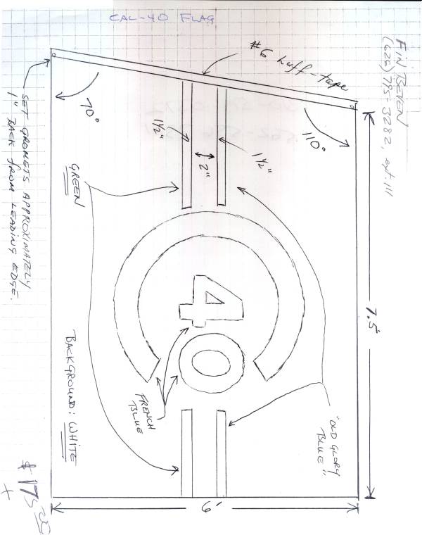 Class Flag Dimension Blueprint
Building & Technical Manuals
How to Build a Cal 40
Comprehensive original construction guide and technical article in PDF format.